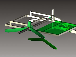


26.1.14
CAD designs of the turning mount.
22.1.14
The rocker-bogie configuration with wheels. The differential bar still needs to be adjusted and properly calculated, but the 1st iteration design is off the ground and rolling! Let's keep up the forward momentum!
22.1.14
Iteration #1 of the rocker-bogie system. To understand the differential bar to be used in the final design along with total angles required for the wheel arm joints. 22.1.14
After some more design iterations, the rover has been put into AutoCAD. This is how the rocker-bogie system will look with a fiberglass cover to protect the internal elements from the elements.
22.1.14
The first generation design of the rover. You may have seen the photo previously come up on our blog. This is the general plan for the rover with a description of each part.


No comments:
Post a Comment